
Pressure Testing Socket-Weld Gauge Guard Assemblies
Factory-validated leak test procedure for TUFF GUARD™ socket-weld gauge guard assemblies using the FasTest EZ Connect™ ZN internal sealing tool. Covers PVC, CPVC, and PVDF bodies in ¼-inch and ½-inch socket configurations.
Pressure Testing Socket-Weld Gauge Guard Assemblies
Purpose & Scope
This bulletin describes the factory-validated leak test procedure for Marquest Tuff Guard socket-weld gauge guard assemblies using the FasTest EZ Connect™ ZN internal sealing tool. It applies to all body materials — PVC, CPVC, and PVDF — in ¼" and ½" socket inlet configurations, and covers two test scenarios:
- Method A — Body-only pre-installation leak test (no instrument installed)
- Method B — Fully assembled leak and accuracy test (instrument installed)
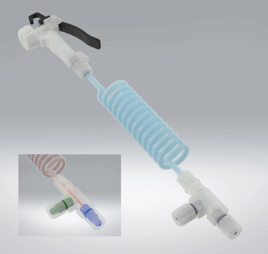
The FasTest ZN seals internally into the process socket bore via lever actuation and introduces a regulated dry, inert gas through an NPT termination port on the tool body. Pressure is applied from the process side, transmitting through the diaphragm to the instrument side. No solvent cementing, permanent bonding, or pipe modification is required. All tooling is reusable.
Testing Rationale
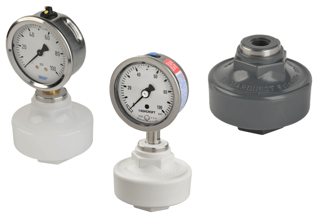
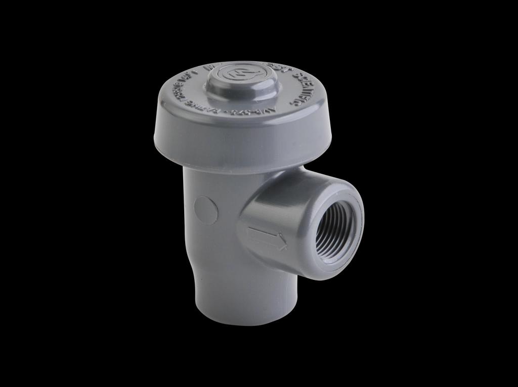
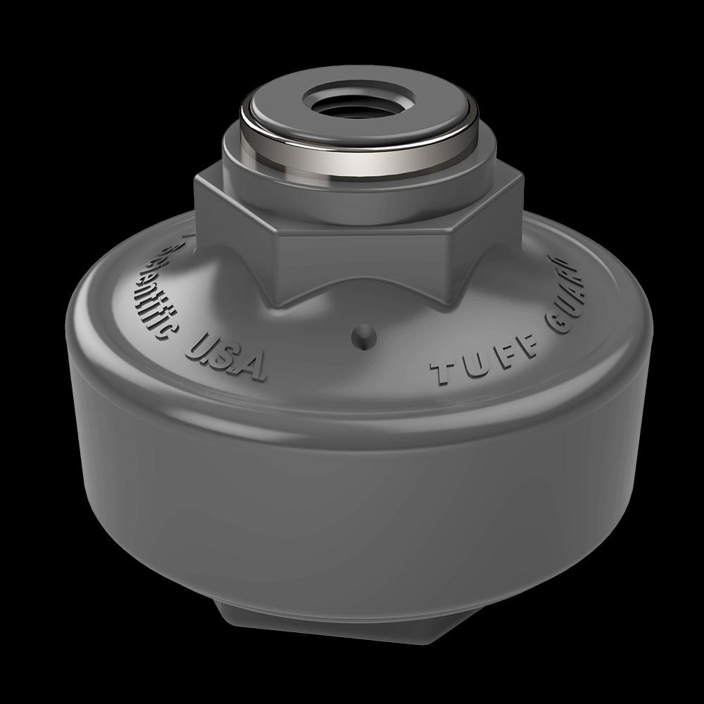
The Tuff Guard diaphragm divides the body into two chambers:
- Lower chamber (process side) — between the diaphragm and the process socket inlet. This is where the FasTest ZN tool seals and where nitrogen is introduced.
- Upper chamber (instrument side) — between the diaphragm and the ¼" Female NPT instrument port. For a body-only test, this chamber is pre-filled with glycerin and capped. For a fully assembled test, the installed instrument seals this chamber and reads the applied pressure directly.
Nitrogen introduced from the process side acts on the lower face of the diaphragm, pushing it upward toward the instrument side. For this to function as a closed, incompressible circuit, the upper chamber must not contain trapped air. In the body-only configuration, glycerin fill and a capped instrument port provide the incompressible upper chamber. In the fully assembled configuration, the installed instrument and its FKM O-ring face seal provide that closure.
Why Socket-Weld Bodies Require Pre-Installation Testing
Socket-weld gauge guard bodies use a permanent process inlet connection — solvent socket for PVC/CPVC, thermal fusion socket for PVDF — rather than a removable threaded connection. Once the body is cemented or fused into a piping system, the process socket is no longer independently accessible for bench testing.
The FasTest ZN procedure described in this bulletin makes pre-installation testing practical and repeatable. Fully assembled accuracy verification under operating pressure can also be performed using this method at up to 50 PSI, with the instrument reading directly against a calibrated reference test gauge.
Note: Threaded-inlet Tuff Guard assemblies can be bench-tested for full-range accuracy by connecting directly through the threaded process port. Contact Marquest for the applicable procedure.
Required Equipment
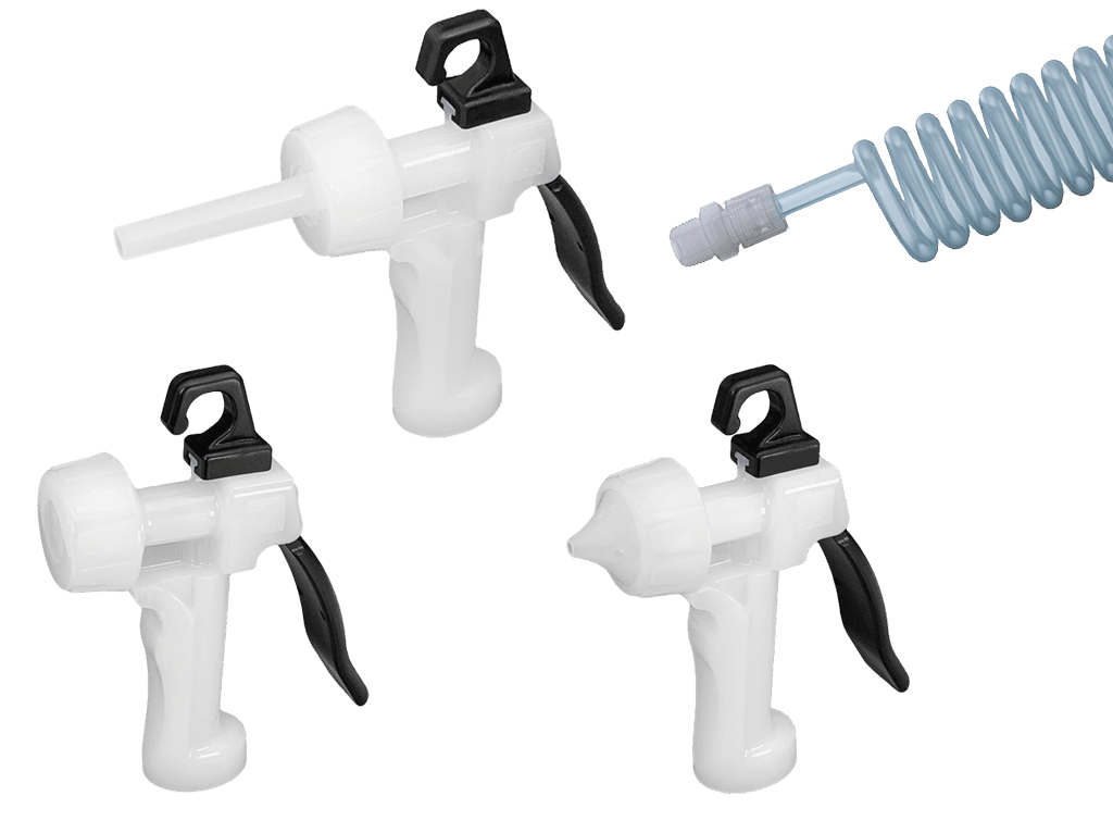
FasTest EZ Connect™ ZN Internal Sealing Tool
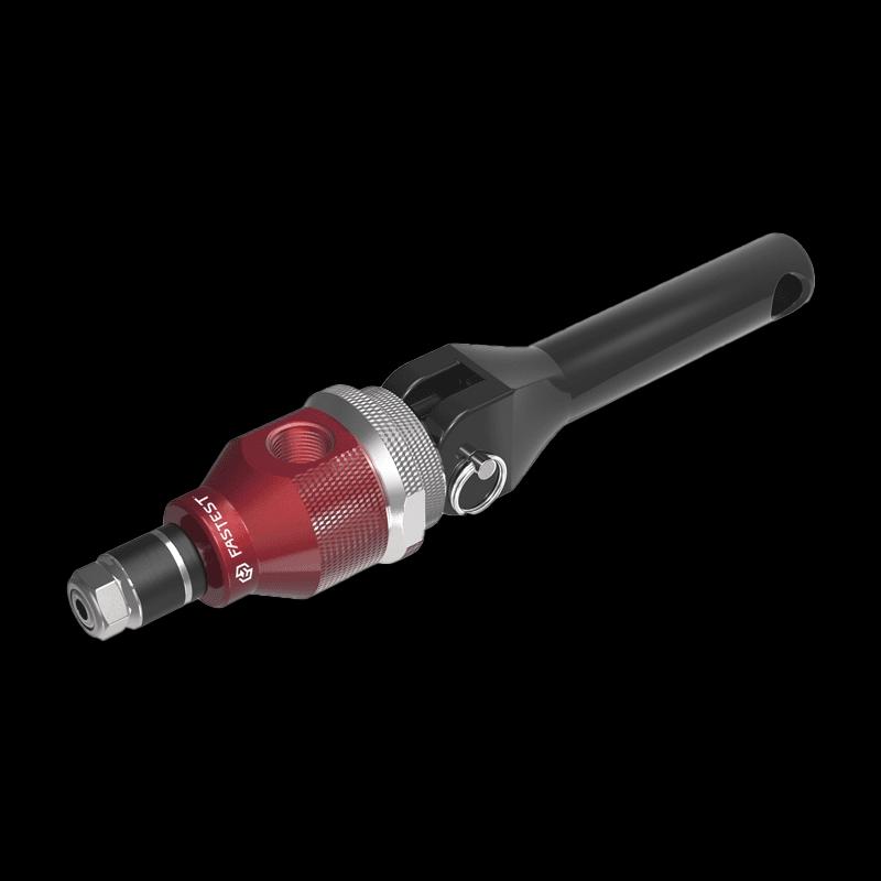
Select the correct part number for socket configuration:
| Specification | ¼" Socket (bore ~0.540") | ½" Socket (bore 0.838"–0.840") |
|---|---|---|
| FasTest Part No. | ZN112 | ZN223 |
| Sealing Range | 0.47–0.55" (12.0–14.0 mm) | 0.79–0.87" (20.0–22.0 mm) |
| Termination Port | ⅛" NPT | ¼" NPT |
| Replacement Seals | ZNB112 | ZNB223 |
| Max Pressure | 50 PSI (3.5 bar) | 50 PSI (3.5 bar) |
| Seal Materials | Neoprene (main) / Buna-N (internal) | Neoprene (main) / Buna-N (internal) |
| Source | fastestinc.com | fastestinc.com |
Additional Equipment
- Regulated dry, inert gas supply with two-stage regulator — dry nitrogen or clean dry air are suitable; do not use oxygen or any moisture-laden gas supply
- Glycerin or glycerin/water mixture (fill fluid — Method A only)
- FasTest MIT042P Manual Twist Connection Tool — plug style, ¼" NPT, 5000 PSI rated, SS/Buna-N/Urethane (Method A only; seals the instrument port while pressurizing from the process side via the ZN tool)
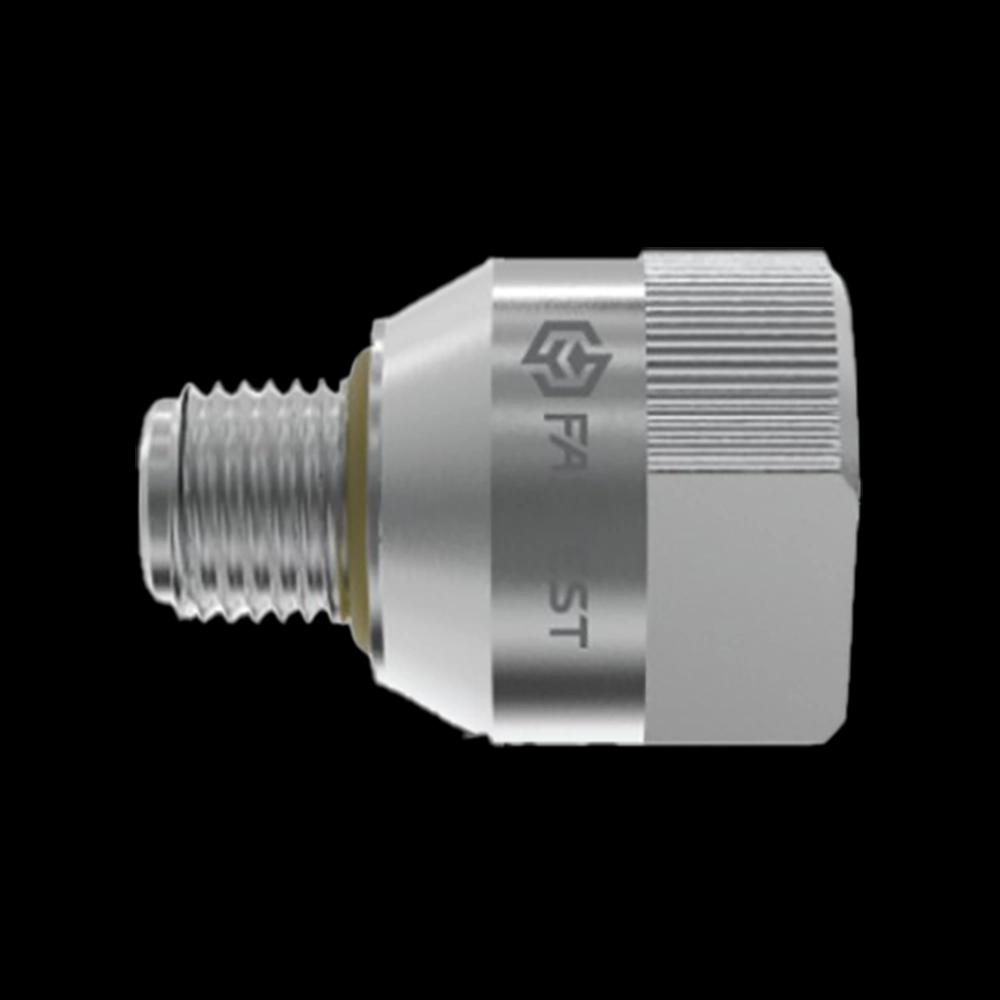
- Calibrated high-accuracy reference test gauge with ¼" NPT connection (Method B only) — ASME Grade 2A or better; full-scale range approximately 2× test pressure
- Non-corrosive soap bubble leak detection solution
Method A — Body-Only Leak Test (No Instrument Installed)
Use this method before installing any instrument. The upper chamber is pre-filled with glycerin to provide an incompressible circuit. The instrument port is capped. Nitrogen is introduced from the process side through the FasTest ZN.
Step A1 — Fill and Purge the Upper Diaphragm Chamber
Orient the gauge guard body with the ¼" instrument port facing up. Fill the upper chamber — the fluid space between the diaphragm and the instrument port — with glycerin or a glycerin/water mixture. Pour slowly until fill fluid appears at the port with no air bubbles, confirming the chamber is completely purged of air.
Critical: The upper chamber must be completely free of air before pressure is applied. Trapped air will compress under nitrogen pressure, causing the diaphragm to overdeflect and permanently deform. Do not proceed until a full, bubble-free purge is confirmed.
Step A2 — Cap the Instrument Port
Install the FasTest MIT042P Manual Twist Connection Tool onto the ¼" instrument port. Twist to engage and seal. The instrument port uses an FKM O-ring face seal — the MIT042P is designed with the correct flat seating face geometry to compress the O-ring and form a positive seal.
Note: A standard tapered NPT cap without a flat seating face will not seal this port.
Step A3 — Install the FasTest ZN into the Process Socket Inlet
Insert the appropriate FasTest ZN tool into the process socket bore. Rotate the lever handle 90° to actuate the internal seal, expanding it against the bore ID. The lockable collar should be set to achieve consistent sealing pressure. Connect your regulated dry gas supply to the termination port on the ZN body (⅛" NPT for ZN112; ¼" NPT for ZN223).
The PVC socket bore is tapered per ASTM D2466 (Schedule 40) — wider at the entrance and narrower at the bottom:
| Dimension | ¼" Socket | ½" Socket |
|---|---|---|
| Socket Entrance Diameter | 0.552" ± 0.004" | 0.848" ± 0.004" |
| Socket Bottom Diameter | 0.536" ± 0.004" | 0.836" ± 0.004" |
| Max Out-of-Round | 0.016" | 0.016" |
| Minimum Socket Length | 0.500" | 0.688" |
| Standard | ASTM D2466 Table 1 | ASTM D2466 Table 1 |
The FasTest ZN sealing ranges — ZN112: 0.47"–0.55" for ¼" sockets, ZN223: 0.79"–0.87" for ½" sockets — cover the full tapered bore with margin on both ends.
Verify the nitrogen regulator is set to the desired test pressure — do not exceed 50 PSI.
Step A4 — Pressurize and Inspect for Leaks
Slowly open the gas supply. Test gas enters the lower chamber and acts on the process face of the diaphragm. With the upper chamber fluid-filled and capped, the assembly behaves as a closed, incompressible circuit. Hold at test pressure for a minimum of 60 seconds.
Apply soap bubble solution to all body joints, the diaphragm-to-body interface, the instrument port cap connection, and around the ZN tool at the socket bore. Inspect each location thoroughly.
Pass Criteria: Zero bubbles at all locations and no pressure decay over the hold period. Any bubble formation at any location, regardless of size or rate, is a failure.
Step A5 — Depressurize, Remove Tooling, and Document
Close the nitrogen supply valve and slowly vent pressure using the regulator bleed. Do not loosen fittings or the ZN tool to vent pressure. Rotate the ZN lever 90° to release, remove from the socket bore, and remove the cap from the instrument port.
Record the following for each unit tested:
- Unit serial or lot number
- Test date
- Test pressure
- Hold duration
- Bubble test result (pass/fail)
- Inspector name
Method B — Fully Assembled Leak & Accuracy Test (Instrument Installed)
Use this method after the instrument has been installed on the ¼" instrument port. The instrument seals the upper chamber via its FKM O-ring face seal and reads the applied nitrogen pressure directly, allowing simultaneous leak verification and instrument accuracy confirmation.
Step B1 — Install the FasTest ZN and Connect Reference Gauge
Insert the appropriate FasTest ZN into the process socket bore and actuate the lever 90° to seal. Connect the regulated dry gas supply to the ZN termination port. Connect a calibrated high-accuracy reference test gauge to a tee in the supply line, downstream of the regulator, so both the ZN and the reference gauge are exposed to the same supply pressure.
Step B2 — Pressurize and Perform Zero-Bubble Soap Test
Slowly raise pressure to the desired test pressure. Isolate the supply by closing the supply valve and allow 60 seconds for thermal stabilization. Apply soap bubble solution to all body joints, the diaphragm-to-body interface, and the instrument port connection. Do not exceed 50 PSI.
Pass Criteria: Zero bubbles at all locations. Any bubble formation is a failure — do not proceed to accuracy verification until a zero-bubble condition is achieved.
Step B3 — Verify Instrument Accuracy
With the zero-bubble test passed and pressure stable, compare the installed instrument reading against the calibrated reference test gauge. Both are reading the same nitrogen pressure transmitted through the diaphragm and fill fluid.
Pass Criteria: Instrument reading is within the manufacturer's specified accuracy tolerance relative to the reference test gauge reading.
Step B4 — Depressurize and Document
Close the nitrogen supply valve and slowly vent using the regulator bleed. Do not loosen fittings or the ZN to vent. Rotate the ZN lever 90° to release and remove.
Record the following for each unit tested:
- Unit serial or lot number
- Test date
- Test pressure
- Hold duration
- Bubble test result (pass/fail)
- Reference gauge reading
- Instrument reading
- Inspector name
Important Notes
-
Air in Upper Chamber (Method A) — The upper chamber must be completely purged of air before the instrument port is capped. Trapped air compresses under nitrogen pressure and will permanently overdeflect the diaphragm, requiring assembly replacement.
-
Maximum Test Pressure — Do not exceed 50 PSI — the maximum rated pressure of the FasTest ZN tool. This pressure range is adequate for both leak verification and instrument accuracy testing across all standard Tuff Guard instrument ranges.
-
Zero-Bubble Standard — This test requires zero bubbles — not merely "no visible drip." Any bubble formation at any location is a failure. The assembly must be repaired and retested before proceeding.
-
Instrument Port — The ¼" Female NPT instrument port is a vented design — threads are intentionally oversized to allow venting, so all pressure sealing is made by the FKM O-ring face seal against a flat seating face. Any cap, plug, or instrument fitting must have a flat seating face. A standard tapered NPT fitting without a flat face will not seal this port.
-
PVDF Bodies — PVDF Tuff Guard bodies use thermal fusion socket joints, not solvent cement. All diaphragm sealing is mechanical, making pre-installation verification especially important.
-
Reference Gauge Selection (Method B) — Use a gauge with a full-scale range of approximately 2× the test pressure. For a 50 PSI test, a 0–100 PSI ASME Grade 2A gauge is appropriate. An oversized range gauge places the test reading in the low-accuracy portion of the dial.
-
Test Medium — Use a dry, inert gas as the test medium. Dry nitrogen or clean dry air (dew point ≤ −40°F / −40°C) are both suitable. Marquest uses dry nitrogen internally. Never use oxygen or any moisture-laden gas supply, as moisture can affect body materials and leave residue in the assembly.
-
Tooling — The FasTest ZN is an engineered production-grade tool designed for OEM and gauge house testing workflows. Replacement seal sets (ZNB112 / ZNB223) are available directly from FasTest. The lockable collar and adjustment ring ensure consistent, repeatable sealing pressure across test cycles.
Marquest Scientific, Inc. — Engineered for Critical Fluids™ Bulletin TB-2026-001 | April 12, 2026