
AQUIS™ Recirculating Spray Gun: Plumbing, Hydraulics & Troubleshooting
Technical guide for the ARSGA recirculating DI spray gun — how the recirculation circuit works, correct plumbing arrangements, why same-loop returns fail, and how installation hydraulics affect microbial contamination risk.
AQUIS™ Recirculating Spray Gun: Plumbing, Hydraulics & Troubleshooting
Overview
The AQUIS™ Recirculating DI Spray Gun is designed to maintain continuous DI water flow through the gun body even when the trigger is not actuated, preventing stagnation in high-purity water systems. This recirculation function depends on a specific hydraulic condition: a pressure differential (ΔP) between the supply inlet and the recirculation return.
When the plumbing arrangement does not provide adequate ΔP, the recirculation circuit can stall — eliminating the very feature the gun was specified to deliver. Stagnant water conditions in a DI water loop create elevated biofilm risk regardless of the materials used in the spray gun itself.
This article explains how the ARSGA recirculation circuit works, what the correct plumbing arrangement looks like, why common field-improvised alternatives fail, and how to interpret the relationship between installation hydraulics and microbial contamination risk.
1. How the ARSGA Recirculation Circuit Works
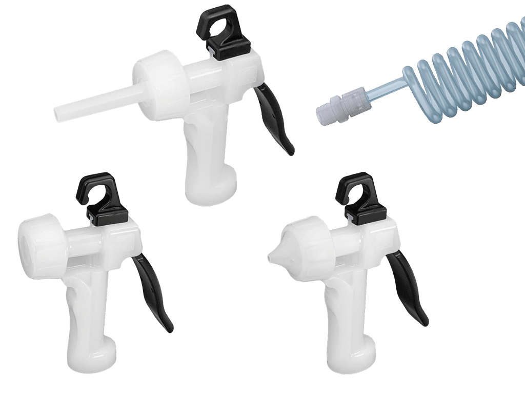
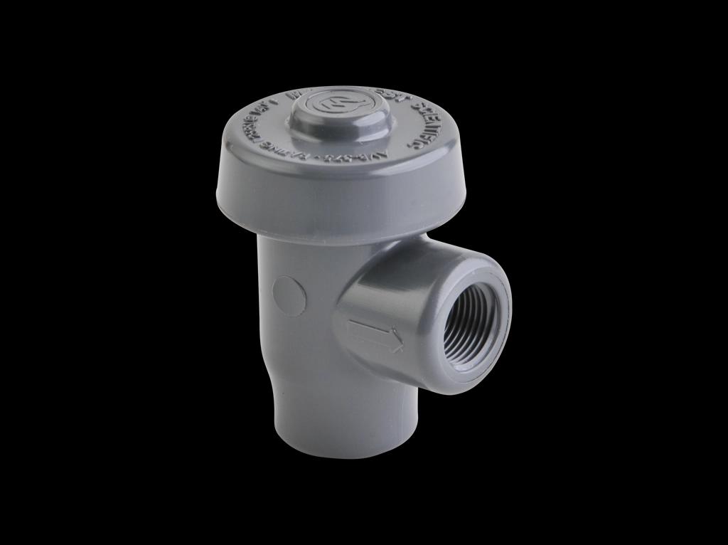
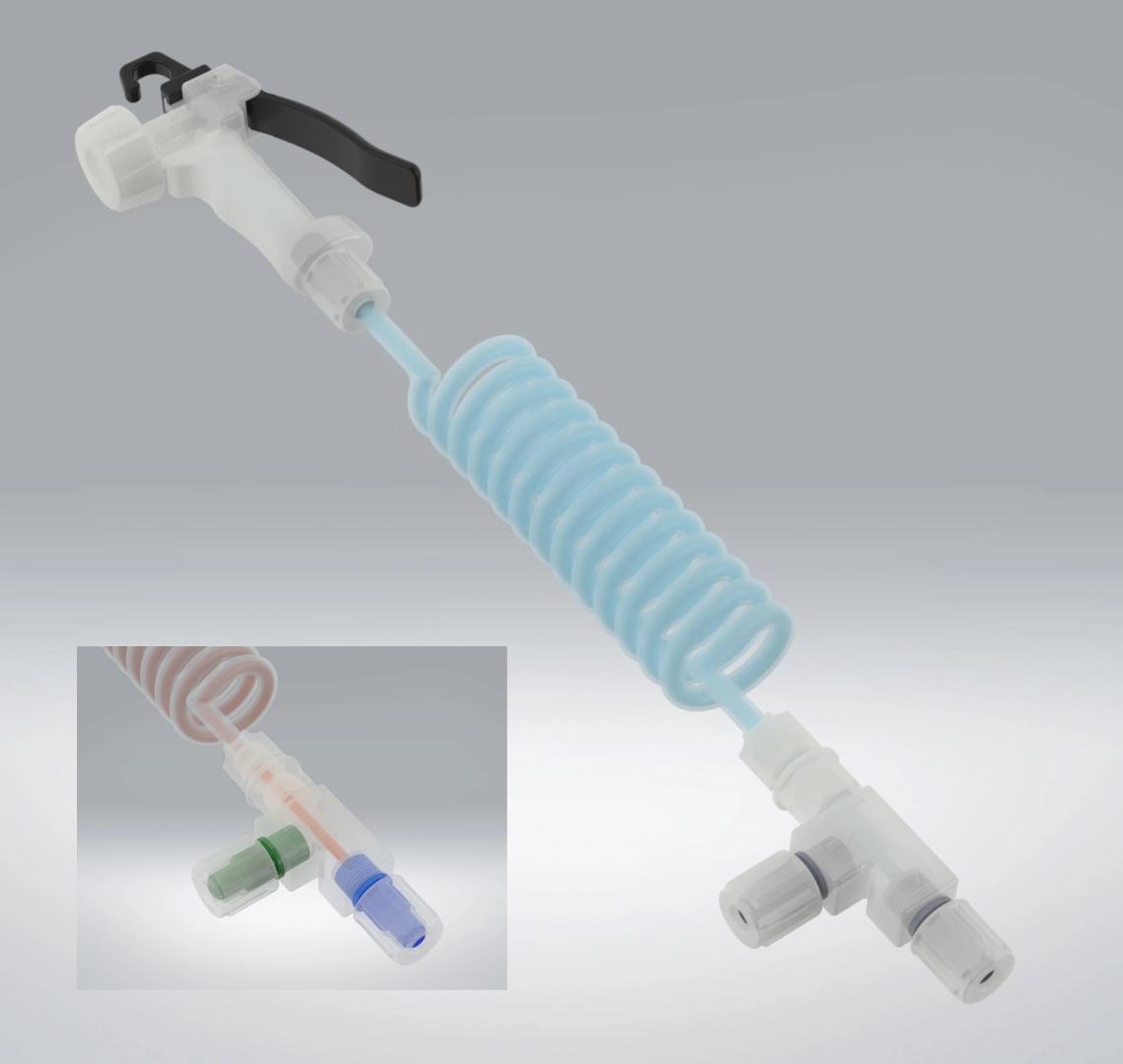
The ARSGA assembly includes a recirculation tee module at the gun inlet. This tee creates a parallel return path that allows DI water to flow continuously through the gun body independent of trigger position.
When the trigger is OFF: Water enters the gun through the supply connection, passes through the tee and gun body, and exits through the recirculation return line. Flow is continuous; no water is stagnant in the gun body.
When the trigger is ON: Most of the flow exits through the spray nozzle. A portion continues through the recirculation path, maintaining flow through the gun even during active spray.
Construction: The ARSGA features an all-virgin PVDF body with a one-piece modified PTFE sealing component. There are no O-rings, elastomers, or lubricants in the wetted flow path — a design that minimizes extractables and supports high-purity DI water service.
The critical operating condition: The recirculation tee creates two parallel flow paths from a single supply. For flow to occur in the recirculation leg, the return connection must be at a demonstrably lower pressure than the supply. The system cannot recirculate against equal or higher backpressure — it requires a net favorable ΔP from inlet to return outlet.
2. The C3-PFA-20R Coiled Assembly: Hydraulic Characteristics
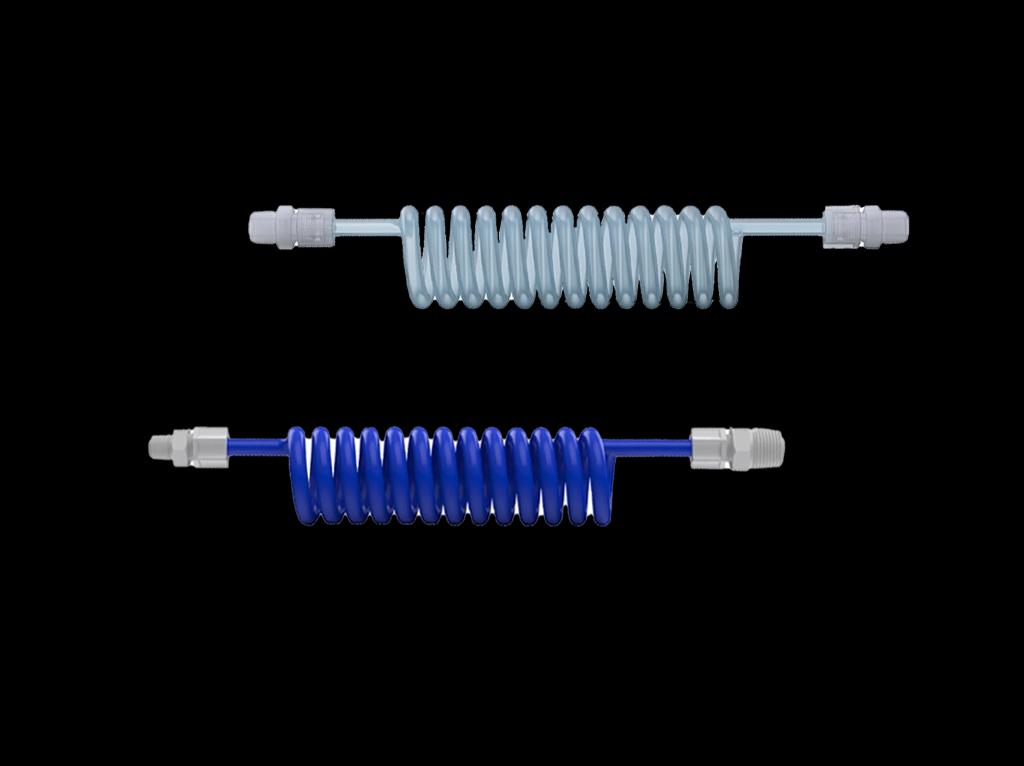
A common ARSGA assembly configuration is the C3-PFA-20R: a 20-foot coiled PFA supply tube (3/8" OD / 1/4" ID) with a dedicated recirculation tube running co-axially inside the coil. The recirculation tube is 0.125" OD × 0.062" ID.
This small inner diameter has a significant hydraulic consequence. The 0.062" ID recirculation tube is highly resistive over its 20-foot length — far more so than the supply tube or the gun body itself. As a result, the recirculation return flow at the coil outlet is substantially lower than the flow measured when the tee is mounted directly at the gun inlet.
At 90 PSI supply with the tee mounted directly at the gun inlet (no coil), the gun delivers approximately 1.65 GPM spray flow and 0.50 GPM recirculation return. Once the full 20-foot coil with 0.062" ID recirc tubing is introduced, the recirc return drops dramatically — most of the available driving pressure is consumed by friction in the small-bore return tube.
Estimated Flow Data — C3-PFA-20R Assembly, Return to Atmosphere
The following values are engineering estimates based on Darcy-Weisbach pressure-drop modeling, using the 90 PSI direct-mount baseline as the calibration point. Actual values will vary with tubing ID tolerance, fitting count, bends, and return backpressure.
Gun ON
| Supply Pressure | Gun Flow (GPM) | Recirc Return Flow (GPM) | Total Supply Flow (GPM) |
|---|---|---|---|
| 30 PSI | 0.84 | 0.048 | 0.89 |
| 60 PSI | 1.20 | 0.060 | 1.26 |
| 80 PSI | 1.39 | 0.070 | 1.46 |
| 90 PSI (ref.) | 1.48 | 0.075 | 1.56 |
Gun OFF
| Supply Pressure | Recirc Flow Only (GPM) |
|---|---|
| 30 PSI | 0.052 |
| 60 PSI | 0.068 |
| 80 PSI | 0.081 |
| 90 PSI (ref.) | 0.087 |
Velocity and Reynolds Number in the 0.062" ID Recirc Tube (Gun OFF)
| Supply Pressure | Recirc Flow (GPM) | Velocity (ft/s) | Reynolds Number | Flow Regime |
|---|---|---|---|---|
| 30 PSI | 0.052 | ~5.4 | ~2,400 | Transitional |
| 60 PSI | 0.068 | ~7.1 | ~3,200 | Transitional |
| 80 PSI | 0.081 | ~8.5 | ~3,800 | Transitional/Turbulent |
| 90 PSI (ref.) | 0.087 | ~9.1 | ~4,100 | Turbulent |
Interpretation: Although the volumetric return flow is small (0.05–0.09 GPM), the velocity in the 0.062" ID tube is 5–9 ft/s, producing transitional-to-turbulent Reynolds numbers. When flowing, this is adequate for stagnation prevention within the recirc tube itself.
The critical distinction: The key metric is not GPM — it is whether flow occurs at all. When the return is to atmosphere, flow occurs. When the return is connected to a same-pressure loop, flow can stall to zero, and the GPM figures above become irrelevant.
3. The Critical Plumbing Requirement: Supply vs. Return Pressure
The recirculation return must discharge to a point at lower pressure than the supply. Acceptable return destinations include:
- Atmospheric drain or floor drain
- Open recovery tank or reservoir
- A return line at a verifiably lower pressure than the supply takeoff
This is not a design limitation unique to the ARSGA — it is a fundamental hydraulic requirement shared by all recirculating DI spray guns. Other manufacturers of recirculating DI spray guns specify similar requirements — return to a recovery tank, drain line, or low-pressure destination. The correct plumbing concept is consistent across manufacturers.
Why the pressure at the recirc outlet is lower than it appears: Even when a gun is supplied from a 45 PSI loop, the pressure remaining at the end of the recirculation tube is a small fraction of supply pressure. By the time water passes through the recirculation tee, the gun body, the 20-foot coil, and 20 feet of 0.062" ID recirc tubing, the frictional losses consume most of the driving head. The static pressure at the recirc return outlet may be only a few PSI — or even less.
If the return connection is made to a point in the supply loop where the local pressure exceeds this residual recirc outlet pressure, one of three outcomes occurs:
- Recirculation flow becomes very small
- Flow becomes unstable or intermittent
- Flow stalls entirely — the recirculation leg carries zero flow
All three outcomes produce stagnant or near-stagnant conditions in the gun body and recirc tubing, which defeats the purpose of the recirculating design.
4. Why a Same-Loop Return Fails — and Why Ball Valves Make It Worse
The Same-Loop Return Problem
Connecting both the supply and the recirculation return to the same pressurized DI loop creates a hydraulic condition where the available ΔP is negligible or zero. Even if the supply branch tees off at 45 PSI, the return branch connection point in the same loop is also at approximately the same pressure. The net driving differential — after subtracting all losses through the gun, tee, and recirc tubing — can be insufficient to sustain flow.
This is not a deficiency in the spray gun. The gun performs as designed when supplied with adequate ΔP. A same-loop supply/return arrangement eliminates the ΔP that the recirculation feature requires.
Ball Valves in DI Water Service
Ball valves are isolation devices. They are designed and rated for fully-open or fully-closed service, not for precision flow throttling or pressure regulation.
In high-purity DI water systems, the use of partially-open ball valves to create artificial pressure drops introduces several problems:
- Dead volume and crevices. Partially-open ball valves create internal geometry with low-flow and no-flow zones — exactly the conditions that high-purity valve design works to eliminate.
- Non-swept regions. Industry guidance from manufacturers such as Entegris emphasizes streamlined, fully-swept flow paths, complete drainability, and elimination of entrapment areas. A throttled ball valve is inconsistent with these principles.
- Inconsistency. A ball valve adjusted to a partially-open position provides no metered, repeatable, or verifiable flow control. The same valve position produces different effective ΔP depending on supply pressure, flow rate, and temperature fluctuations.
- Maintenance risk. A valve position that appears to produce recirculation at one operating condition may not maintain it as system conditions change.
Using multiple ball valves to simulate the pressure differential that a proper return path provides is not an engineered solution — it is an improvisation that introduces its own contamination risks.
For comparison: Some manufacturers of recirculating faucets that use same-loop supply and return connections address this with a purpose-engineered inline flow diverter that creates a controlled, predictable ΔP. The diverter is a required part of the product architecture — not an optional accessory. This is the correct approach for same-loop return: a validated engineered device, not field-adjusted ball valves.
5. Microbial Contamination: System-Level Attribution
Bacterial contamination in DI water systems is a system-level phenomenon. It is not attributable to any single component in isolation, including the spray gun.
Stagnation is a contributing factor to biofilm. Recirculating spray guns reduce stagnation by maintaining flow through the gun body. But this benefit is only realized when the hydraulics actually produce flow. If the recirculation circuit is stalled due to incorrect plumbing, the spray gun body becomes a dead leg — stagnant water in contact with exposed surfaces.
Recirculation reduces stagnation risk but does not eliminate microbial risk. Even with proper recirculation and verified flow, biofilm can develop in recirculating water systems. Microbial control in DI water loops depends on overall system design, water quality, temperature, material selection, dead-leg elimination, and sanitization protocols. CDC guidance notes that biofilms can develop under both stagnant and flowing conditions.
The correct characterization of the recirculation feature is: it reduces stagnation and lowers biofilm risk within the gun body when properly plumbed. It should not be described as a guarantee against bacterial contamination.
When investigating contamination in a recirculating DI system, the assessment should include:
- Whether the recirculation circuit is actually flowing (verify with an in-line flow indicator on the return line)
- Whether the return pressure is genuinely lower than the supply pressure (measure, do not assume)
- Whether any dead legs, low-flow zones, or stagnant sections exist in the broader loop
- Whether the system includes microbial control measures (UV sterilization, ultrafiltration, periodic hot-water or chemical sanitization)
- Whether the installation uses piping components consistent with high-purity DI water design standards
6. Correct Installation: The Recommended Plumbing Arrangement
Supply Connection
Branch-tee from the DI supply loop directly to the ARSGA inlet connection. No throttling devices are required or recommended downstream of the branch tee.
The gun will receive approximately the local loop pressure at the branch point, minus normal pressure losses through the branch tubing, tee module, and gun internals. This is expected and normal — it does not indicate a problem. The gun does not require an additional downstream restriction to operate.
Recirculation Return Connection
The recirculation return line should discharge to one of the following:
- Atmospheric drain (floor drain, open funnel drain, drain line at atmospheric pressure)
- Recovery tank or open reservoir (non-pressurized)
- A return line at a verifiably lower pressure than the supply branch point — measured, not estimated
Isolation Valves (If Required)
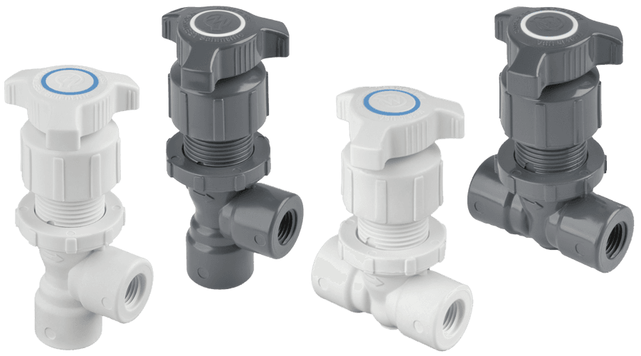
If isolation valves are used for maintenance access, they should be full-port ball valves in the fully-open position during normal operation. They are appropriate for service isolation only. No throttling of the recirculation circuit is required or appropriate.
What Not to Do
- Do not connect the recirculation return to the same pressurized supply loop without an engineered pressure-reducing device
- Do not use ball valves as throttling or pressure-drop devices in the recirculation circuit
- Do not assume the available supply pressure at the gun equals the pressure available to drive recirculation at the return outlet — these are different values separated by significant frictional losses
7. When a Same-Loop Return Is Unavoidable
Some facilities — particularly those with closed recirculating DI systems and no atmospheric storage tank — may have no readily available low-pressure return point.
If a same-loop return arrangement is the only available option, the installation requires an engineered pressure-reducing device (not a ball valve) to create a reliable, measurable ΔP across the recirculation circuit. This is analogous to the inline flow diverter approach used by some recirculating faucet manufacturers: a purpose-designed device that creates predictable differential pressure, installed in a defined location, with verifiable performance.
Requirements for a same-loop return arrangement:
- The pressure-reducing device must be engineered for the application, not improvised from throttled valves
- The resulting ΔP must be measurable and consistently maintained across normal operating conditions
- Recirculation flow should be verified with an in-line flow indicator on the return line before commissioning
- The arrangement should be reviewed by a qualified system engineer familiar with high-purity water system design
Contact Marquest Engineering if you are designing a same-loop return installation and need guidance on whether adequate ΔP can be achieved.
8. Frequently Asked Questions
Q: Does the spray gun require a specific downstream pressure drop to work? A: No. If the recirculation return discharges to atmosphere or a lower-pressure destination, the required ΔP is already provided by the difference between the loop supply pressure and the return pressure. No additional restriction is needed.
Q: The recirc return flow seems very low (0.05–0.09 GPM). Is the gun defective? A: No. With the 20-foot C3-PFA-20R coiled assembly and 0.062" ID recirc tubing returning to atmosphere, 0.05–0.09 GPM is the expected return flow across the normal supply pressure range. The velocity in the recirc tube at those flow rates (5–9 ft/s) is adequate for stagnation prevention. The relevant question is whether flow exists at all — not whether the GPM matches the flow at the tee-direct configuration.
Q: If there's a bacterial contamination issue, is the spray gun the source? A: Bacterial contamination in DI water systems is system-level in origin. A spray gun installed in a stagnant dead leg (due to a stalled recirculation circuit) may harbor biofilm — but so will any other stagnant section of the loop. The investigation should address the full system, including plumbing arrangement, recirculation flow verification, and the presence or absence of microbial control measures in the loop.
Q: Can the recirculating tee module be relocated further from the gun? A: The tee module location affects the pressure available to both the gun and the recirculation leg. Moving the tee further from the gun increases the supply-side pressure drop before the branch split, reducing flow at both outlets. Consult Marquest Engineering for guidance on non-standard tee placement.
Contact Marquest Engineering
For application-specific installation questions, pressure and flow verification, or guidance on same-loop return configurations, contact Marquest Engineering directly:
Marquest Scientific, Inc. Toll Free: (866) 452-2349 x1100 www.marquestscientific.com Manufactured & Assembled in Costa Mesa, CA USA
This article reflects engineering guidance based on the hydraulic principles governing the ARSGA product family. All flow values are engineering estimates. Actual performance depends on installation-specific factors including supply pressure, tubing dimensions, fitting count, and return backpressure. Verify recirculation flow in the installed configuration before commissioning.