
Mating Plastic NPT Threads on Throttle Master™ Needle Valves
Complete installation guide for mating plastic Male NPT fittings to Female NPT ports on Throttle Master™ Needle Valves in PVC, CPVC, PPR, and PVDF materials.
Mating Plastic NPT Threads on Throttle Master™ Needle Valves
1. Purpose and Scope
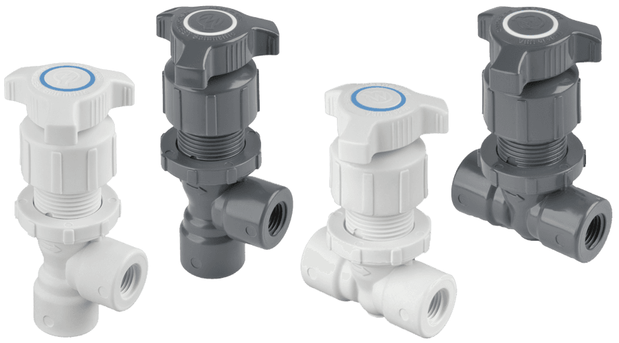
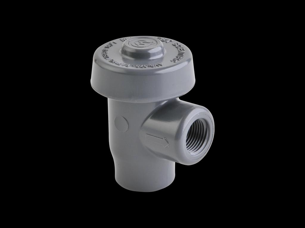
This document defines standard installation practices for mating plastic Male NPT (MNPT) fittings to plastic Female NPT (FNPT) ports on:
- Throttle Master™ Needle Valves
- With 1/4", 3/8", and 1/2" FNPT ports
- In PVC, CPVC, Glass & Mineral Reinforced Polypropylene (PPR), and PVDF
The goal is to provide repeatable, engineering-based guidance that:
- Minimizes installer guesswork
- Reduces thread-related field issues
- Standardizes how we talk about “finger-tight + turns” for plastic threads
Out of scope:
- Metal MNPT × plastic FNPT (use separate transition guidelines)
- Thread standards other than NPT (e.g., BSPT, metric)
- Sizes larger than 1/2" NPT
2. NPT Thread Basics (Context)
Throttle Master™ FNPT ports and standard MNPT fittings use ANSI/ASME B1.20.1 NPT thread geometry:
- Thread angle: 60°
- Taper: 1:16 (3/4" per foot)
- Taper function: creates the interference fit that provides sealing
- Pitch (common sizes used here):
- 1/4" NPT: 18 TPI
- 3/8" NPT: 18 TPI
- 1/2" NPT: 14 TPI
Key difference vs. metal
- Metal fittings: Often tightened to a “feel” that includes higher torque and more deformation at the thread crest.
- Plastic fittings/ports: Must be controlled by turn count from finger-tight, not by torque, to avoid excessive hoop stress and long-term creep at the FNPT boss.
3. Design Basis for Throttle Master™ Ports
For Throttle Master™ Needle Valves:
- Wall sections, boss diameters, and thread relief are designed to meet appropriate NPT engagement while maintaining structural integrity.
- For PVC, CPVC, PPR, and PVDF versions, the FNPT port geometry is functionally comparable (i.e., same basic wall section and thread relief for a given size).
- The installation guidance is therefore unified by size and material family, with slightly more conservative turn limits specified for PVDF as a long-term stress control measure rather than a statement that PVDF is “weaker” or “more fragile.”
4. Core Principles
-
Start by hand, finish by counted wrench turns.
- No tools for initial engagement.
- Wrench only after finger-tight is reached, and count turns.
-
Sealant is a fit and sealing aid – not a substitute for controlled tightening.
- Use plastic-compatible, non-hardening sealant and/or properly applied PTFE tape.
-
Plastic–plastic only (for this guide).
- All guidance assumes plastic MNPT × plastic FNPT.
- Metal adapters require separate instructions.
-
Never use the valve body as an alignment lever.
- Do not twist the entire valve against rigid piping to pull a run into alignment.
- Correct piping alignment before final make-up.
5. Turn Limits (By Material)
These limits apply to:
- 1/4" FNPT Throttle Master™ ports
- 3/8" FNPT Throttle Master™ ports
- 1/2" FNPT Throttle Master™ ports
mated with plastic MNPT fittings (e.g., closed nipples, hex nipples) of the same NPT size.
5.1 PVC, CPVC, PPR
- Finger-tight + 1 to 1¼ wrench turns
- Absolute maximum: 1½ wrench turns beyond finger-tight
5.2 PVDF
- Finger-tight + up to 1 wrench turn
- Absolute maximum: 1 wrench turn beyond finger-tight
These limits are specification choices to control localized thread stress and long-term creep behavior. They are not intended as a statement that PVDF is inherently weaker than PVC, CPVC, or PPR; they are conservative, unified installation rules for our product line.
6. Sealant Options and PTFE Tape Guidance
6.1 Non-Hardening Joint Compound (Preferred Baseline)
Use a non-hardening pipe joint compound that is:
- Explicitly approved for PVC/CPVC/PP/PVDF
- Compatible with the process fluid
- Certified where required (e.g., NSF/ANSI)
Avoid on plastic threads:
- Hard-setting sealants
- Solvent-rich dopes not listed for plastic use
- Anaerobic “thread-lock” sealants intended for metal
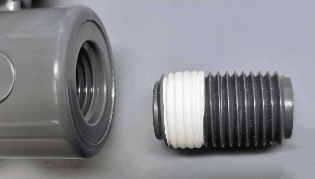
6.2 PTFE Tape – Controlled Application
Plastic NPT joints often use PTFE tape for fit and seal. For 1/4", 3/8", and 1/2" plastic MNPT fittings:
-
Use non-stretched, high-quality USA-made PTFE tape
-
Tape width by size (typical):
- 1/4" MNPT fitting → 1/4" PTFE tape
- 3/8" MNPT fitting → 3/8" PTFE tape
- 1/2" MNPT fitting → 1/2" PTFE tape
-
Wrap count:
- Standard: 2–3 wraps
- If male threads are on the low side of NPT tolerance: up to ~3.5 wraps
- Always in the direction of tightening so the tape lays into the thread
-
Leave the first thread crest at least partially visible where practical so the profile is clear and tape isn’t bunched at the end.
Important:
PTFE tape is a fit/seal aid, not permission to overtighten.
Turn limits in Section 5 still apply.
7. Installation Procedure (Step-by-Step)
Step 1 – Inspect and Verify Components
-
FNPT port (Throttle Master™ valve):
- Verify size (1/4", 3/8", or 1/2" FNPT)
- Check for:
- Clean, dry threads
- No chips, debris, or plastic shavings
- No flattened, galled, or heavily damaged threads
-
MNPT fitting (plastic nipple/fitting):
- Verify NPT size and standard (NPT, not BSPT, etc.)
- Confirm material (PVC, CPVC, PPR, PVDF, etc.) matches the application
- Check threads for molding flash, nicks, or damage
-
Application check:
- Confirm material selection vs. fluid, pressure, and temperature
- Respect derating curves for thermoplastic materials
Step 2 – Apply Sealant to Male Threads Only
-
Joint compound option:
- Apply a thin, even coat to MNPT threads only.
- Avoid flooding the thread root; do not allow blobs that can be pushed into the system.
-
PTFE tape option:
- Hold the fitting and wrap tape in the direction of tightening.
- Use the width appropriate to size (e.g., 1/4" tape on 1/4" nipple).
- Apply 2–3 wraps (up to ~3.5 if the fit is loose in tolerance).
- Keep tape neat; avoid overlaps and bunching.
-
Do not apply sealant to FNPT threads inside the valve body.
Step 3 – Start the Joint by Hand
- Align the MNPT fitting with the FNPT port squarely.
- Turn by hand only for the first several turns:
- Engagement should feel smooth and progressive.
- No grinding, binding, or “jumping” of the threads.
If it does not turn smoothly by hand:
- Stop.
- Back off the fitting completely.
- Inspect threads and sealant.
- Correct alignment or replace damaged parts; do not “force it straight” with a wrench.
Step 4 – Wrench Make-Up (Controlled Turns)
Once you reach finger-tight (firm resistance by hand):
-
Place a wrench on the MNPT fitting:
- For a hex nipple: use the hex section.
- For a closed nipple: use an appropriate wrench or smooth-jaw tool on the body (not on the taped threads).
-
Support the valve body:
- Hold the valve by hand close to the port, or
- Use a strap wrench or soft jaws on a non-critical surface if extra support is needed.
- Do not torque the valve against rigid piping as a lever.
-
Tighten by counted wrench turns from finger-tight using the limits in Section 5:
-
PVC / CPVC / PPR
- Finger-tight + 1 full wrench turn, then evaluate
- If needed, up to 1¼ turns
- Never exceed 1½ turns
-
PVDF
- Finger-tight + ¾ to 1 full wrench turn
- Do not exceed 1 turn
-
-
If resistance increases sharply before you reach the target turn count, or you feel yourself “forcing” the connection:
- Stop
- Reassess:
- Sealant / tape application
- Correct thread standard and size
- Component condition (damage, contamination, etc.)
8. Closed Nipple vs. Hex Nipple (Plastic MNPT)
Both plastic closed nipples and plastic hex nipples are used for mating into Throttle Master™ FNPT ports.
8.1 Plastic Closed Nipple
- Male NPT on both ends, fully threaded, no central hex.
- Advantages:
- Very compact length
- Useful for close-coupled assemblies
- Considerations:
- No dedicated wrench flats — must grip the body carefully
- Use smooth jaws or appropriate wrench surfaces to avoid damaging threads
- Extra care required not to crush or ovalize the nipple while wrenching
8.2 Plastic Hex Nipple
-
Male NPT on both ends with a hex section between.
-
Advantages:
- Clear wrench surface for controlled torque
- Easier to assemble and disassemble consistently
- Reduced risk of damaging thread crests
-
Recommended where:
- Space allows
- Frequent removal is expected
- Tight control over assembly is needed
Both types are acceptable when:
- Installed inside the turn limits
- Supported properly
- Fitted with appropriate sealant / tape
9. Visual Acceptance Criteria
After tightening:
-
Threads visible:
- Typically 1–3 male threads remain visible outside the port.
- The fitting should not be visually “buried” deep into the boss.
-
Port region appearance:
- No obvious distortion, bulging, or whitening around the FNPT boss.
- No cracks or crazing visible at or near the port.
-
Fitting orientation:
- Joint appears aligned and square.
- No evident bending moment being taken by the valve body.
10. Material-Specific Notes
These notes apply specifically to Throttle Master™ Needle Valves and similar Marquest components in 1/4", 3/8", and 1/2" FNPT sizes.
10.1 PVC
- Common in water treatment and general industrial service.
- Typical continuous temperature limit ~60 °C (140 °F) with pressure derating.
- Works well with:
- Non-hardening compound
- PTFE tape (2–3.5 wraps)
- Turn limit: finger-tight + 1–1¼ wrench turns (max 1½)
10.2 CPVC
- Higher temperature capability than PVC (often ~90–95 °C / 194–203 °F depending on design/standard).
- Same general installation behavior and turn limits as PVC.
- Turn limit: finger-tight + 1–1¼ wrench turns (max 1½)
10.3 PPR (Glass & Mineral Reinforced Polypropylene)
- Reinforced PP for greater stiffness and dimensional stability.
- Suited for many corrosive fluids when properly selected.
- Stiffer material → rely on fit and controlled make-up, not additional torque.
- Turn limit: finger-tight + 1–1¼ wrench turns (max 1½)
10.4 PVDF
- Excellent chemical resistance and broad temperature capability.
- Throttle Master™ PVDF valves use comparable wall sections and thread relief to their PVC/CPVC/PPR counterparts for a given size.
- For long-term stress control and consistency, we specify:
- Finger-tight + up to 1 wrench turn
- No more than 1 wrench turn beyond finger-tight
11. Quick Reference – Field Rules
For 1/4", 3/8", 1/2" Throttle Master™ FNPT ports with plastic MNPT fittings:
-
Start every joint by hand.
- Use hand force only for the first several turns.
- If it doesn’t turn smoothly, stop and realign before using tools.
-
Sealant:
- Use plastic-approved, non-hardening joint compound
- or non-stretched USA PTFE tape (2–3.5 wraps, width matched to fitting size)
- Apply to male threads only.
-
After finger-tight, tighten with a wrench by counted turns:
- PVC / CPVC / PPR:
- +1 to +1¼ wrench turns (max 1½)
- PVDF:
- +¾ to 1 wrench turn (max 1)
- PVC / CPVC / PPR:
-
Support the valve body.
- Hold by hand near the port or use strap/soft jaws on non-critical surfaces.
- Do not use the valve as a lever to pull piping into alignment.
-
Final check:
- 1–3 threads visible, no distortion or cracking at the boss, and the assembly looks square and relaxed.
When these rules are applied consistently, plastic NPT connections on Throttle Master™ Needle Valves become a controlled, engineered joint rather than a variable dependent on installer feel.