Marquest ScientificFamily owned since 1978. Molded in Anaheim, assembled and tested in Costa Mesa, California.

Try a part number
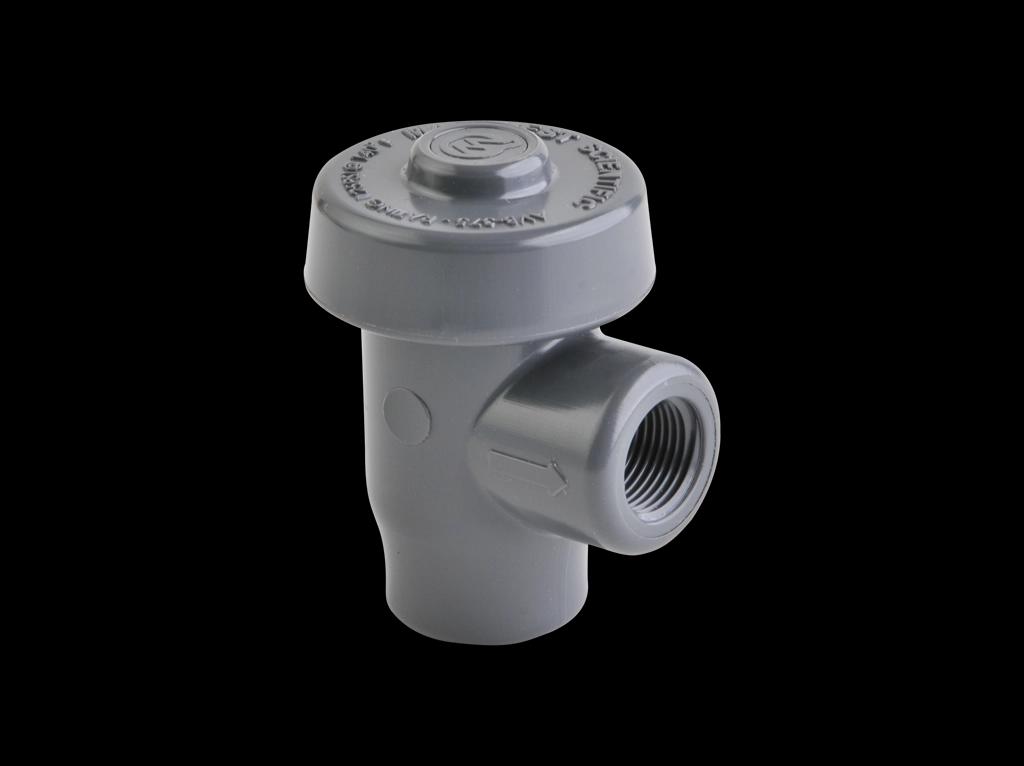


Mini TUFF GUARD® Isolators
Installation Instructions
Document: MTG-INS-001 Rev. B
Important Safety Information
Read all instructions carefully before installation. Ensure system is depressurized before beginning work. Use appropriate personal protective equipment (PPE) when handling chemicals or pressurized systems. Verify chemical compatibility of all materials with your specific application.
Dry Chlorine Gas Warning
Mini TUFF GUARD Isolators are NOT recommended for dry chlorine gas service.
Since thermoplastics are made from hydrocarbon-based materials, most plastics—including PVC, CPVC, and PP—will react chemically with dry chlorine. These reactions can be vigorous and dangerous, potentially resulting in the uncontrolled release of chlorine gas.
This restriction applies to dry chlorine in either the liquid or gaseous phase. Chlorinated water (wet chlorine) is acceptable—when moisture is present, these materials exhibit better chemical tolerance.
Pre-Assembled Units
If you purchased your Mini TUFF GUARD Isolator with an instrument pre-installed from Marquest Scientific, the assembly has already been filled and is ready for use. Skip directly to System Installation.
Section A: Materials of Construction
| Component | Material Options |
|---|---|
| Body | PVC, CPVC, PP, or PVDF |
| Diaphragm (Media Side) | PTFE/FKM Composite (PTFE) |
| Diaphragm (Instrument Side) | FKM |
Compatible Instruments
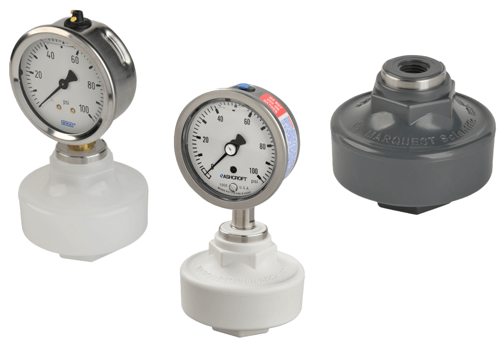
- Analog Pressure Gauges – 2.5" diameter (63mm) dial case or smaller only
- Compact Pressure Transmitters
- Pressure Transducers
- Pressure Switches
Instrument Size Restriction
Mini TUFF GUARD Isolators should ONLY be used with analog pressure gauges having a dial case diameter of 2.5 inches (63mm) or smaller. Larger gauges require more fill fluid displacement volume than the Mini TUFF GUARD can provide.
Section B: Filling the Upper Chamber (Isolator)
The upper chamber (above the diaphragm) must be filled with a liquid compatible with the instrument, isolator, diaphragm, and operating conditions.
Compatible Fill Fluids
- Aqueous glycerine (70% 99% FDA Food Grade Glycerin / 30% Distilled Water) – Our standard fill
- Mineral oil
- Silicone oil
- Distilled water
- Fluorocarbon Oil (Halocarbon 4.2 Oil) – For sodium hypochlorite, chlorine and other strong oxidizers
Procedure
- 1Locate the orifice at the bottom of the instrument thread.
- 2Carefully add fill liquid through the orifice, taking care not to bridge the orifice and trap air in the upper chamber.
- 3Continue filling until the liquid level is just above the O-ring instrument seal.
- 4Inspect for air bubbles and repeat if necessary.
Section C: Filling the Instrument
The instrument internal cavity must be filled with the same fill fluid used in the isolator upper chamber. Complete removal of air is critical for accurate pressure measurement. Even a small air bubble (as small as a grain of rice) can cause significant measurement errors.
| Instrument Type | Filling Difficulty | Recommended Method |
|---|---|---|
| Analog Gauge | More difficult – Bourdon tube can trap air | C.1 Manual or C.2 Vacuum method |
| Transmitter | Easier – Small cavity fills readily | C.3 Direct fill with orifice bridging |
| Transducer | Easier – Small cavity fills readily | C.3 Direct fill with orifice bridging |
| Pressure Switch | Easier – Small cavity fills readily | C.3 Direct fill with orifice bridging |
C.1 Analog Gauges – Manual Fill
Analog gauges contain a Bourdon tube – a curved, sealed tube that straightens under pressure to move the pointer. The closed end can trap air, making complete filling more challenging.
- 1Invert the gauge (dial face down).
- 2Add fill fluid through the instrument orifice using a syringe or squeeze bottle.
- 3To vent trapped air: Cover the orifice with your thumb while keeping the gauge face toward your palm.
- 4Shake vigorously up and down to dislodge air bubbles from the Bourdon tube.
- 5Remove thumb, add additional fluid to replace displaced air.
- 6Repeat steps 3–5 until no more air bubbles emerge when shaking.
C.2 Analog Gauges – Vacuum Fill (High-Accuracy)
Recommended when high accuracy is required or when the manual method fails to remove all air. Requires a vacuum filling station or manifold.
- 1Connect the gauge to a vacuum manifold via the pressure port.
- 2Place the fill fluid reservoir below the gauge in the vacuum chamber.
- 3Evacuate the system to approximately 28" Hg vacuum.
- 4While maintaining vacuum, slowly rotate or manipulate the gauge to help trapped air escape.
- 5Open the fill fluid valve to allow degassed fluid to be drawn into the evacuated Bourdon tube.
- 6Slowly release vacuum and verify the gauge is completely filled.
Why Vacuum Filling?
Under vacuum, trapped air expands and escapes more readily. When fill fluid is introduced under vacuum, it flows into the evacuated space without trapping air pockets. This is especially important for low-pressure ranges.
C.3 Transmitters, Transducers & Switches – Direct Fill
Electronic pressure sensors typically have a small cylindrical dead leg cavity below the actuating diaphragm. This simple geometry fills more easily than the curved Bourdon tube found in analog gauges.
- 1Invert the sensor (process connection facing up).
- 2Using a syringe or dropper, add fill fluid through the orifice until the cavity is full.
- 3Gently tap the sensor body to release any trapped air bubbles.
- 4Top off with additional fluid as needed.
- 5Bridge the orifice: Apply vacuum grease or Vaseline across the orifice to create a temporary seal.
- 6Keep the sensor inverted until ready to assemble to the isolator.
Tip: Orifice Bridging
A thin film of vacuum grease or Vaseline across the sensor orifice acts as a temporary seal during assembly. The grease will be displaced and dissolve into the fill fluid without affecting measurement accuracy.
Critical Note
NEVER use thread sealant of any type on the instrument thread! The instrument seals on the O-ring provided at the bottom of the female instrument thread. This is a venting thread that allows pressure to escape during assembly.
Section D: Assembling the Instrument to the Isolator
- 1Ensure both the isolator upper chamber and instrument are properly filled per Sections B and C.
- 2Invert the filled instrument (for electronic sensors, the orifice should be bridged with grease).
- 3Carefully align and thread the instrument into the ¼" NPT female venting thread on the isolator.
- 4Continue threading until the instrument bottoms against the O-ring and increased resistance is felt.
- 5Hand tighten only. Do not use tools to tighten the instrument connection.
- 6Orient the gauge or sensor display for optimal viewing angle before final hand tightening.
Section E: System Installation
- 1Apply 3 to 4 wraps of high-density PTFE thread sealant tape to the male thread of the isolator or the male thread of the system connection.
- 2Join the instrument/isolator assembly to the system by threading together.
- 3Tighten using the larger diameter of the upper chamber of the isolator OR the wrench flats provided on the lower chamber.
- 4Verify the installation is leak-free before pressurizing the system.
Warning
Do NOT tighten or loosen using the instrument. When removing the assembly from the system, use ONLY the wrench flats provided on the lower chamber. Using the instrument body or gauge case as a leverage point can damage the instrument or break the seal.
Section F: Quick Reference Summary
DO ✓
- Use gauges 2.5" (63mm) or smaller
- Fill chamber above O-ring level
- Remove all air from instrument
- Use vacuum grease to bridge sensor orifice
- Hand tighten instrument to isolator
- Use PTFE tape on system threads
- Use wrench flats for removal
DO NOT ✗
- Use gauges larger than 2.5" (63mm)
- Trap air in chambers or instrument
- Use thread sealant on instrument thread
- Over-tighten with tools
- Tighten or loosen using the gauge/sensor
- Use incompatible fill fluids or chemicals
- Skip leak testing after installation
Section G: Troubleshooting
| Symptom | Likely Cause / Solution |
|---|---|
| Gauge reads erratically or sluggishly | Air trapped in system. Disassemble and refill using vacuum method for gauges, or repeat fill procedure for sensors. |
| Gauge needle doesn't return to zero | Air in Bourdon tube, or gauge may have been over-pressured. Try vacuum refilling. Replace gauge if damage suspected. |
| Fluid leaks at instrument thread | O-ring damaged or missing. Check O-ring condition and reseat. Do not use thread sealant – it interferes with proper sealing. |
| Transmitter output drifts | Air in fill system or incompatible fill fluid. Verify fill fluid compatibility and refill system completely. |